18XT Suspension Structures
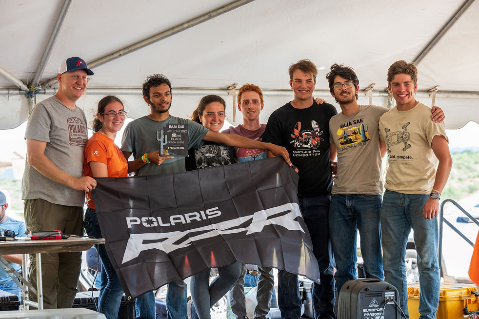
I was the Suspension Lead Engineer for the 18XT, the Johns Hopkins University's first top-10 car in the past five years. Over its three competitions, the car won the following awards while competing against more than 100 teams (some international!):
TENNESSEE 2022:
Design - 1st Place
Static Events - 3rd Place
ROCHESTER 2022:
Design - 2nd Place
Static Events - 4th Place
ARIZONA 2023 (as Team Captain):
Design - 2nd Place
Overall - 8th Place
.jpeg)
Above: 2nd Place Design Event at Arizona 2023
Below: Suspension, Steering, Brakes Design Poster
OVERVIEW

As the Suspension Lead Engineer for the 18XT, I went in with the following goals to improve the subsystem:
-
Develop analysis methods for components to accurately model actual on-car loads;
-
Iterate and improve previous years components to retain system reliability;
-
Aggressive design on non-critical or easily-replaceable components to save weight.
UPRIGHTS


One of the biggest improvements I made in the rear upright design process was the overhaul of analysis.
Firstly, I accounted for the effective moment arm provided by the tire, and applied it to the cornering loading scenario. I also processed and filtered loading data to more accurately define loads, finding a 32% decrease in our expected cornering force.
Running these loads on the previous year's upright recreated a failure that was actually seen during competition - showcasing the accuracy of this analysis method.
These changes led to me changing the lower mount to a rectangle tube, placing the most material in locations where it is needed to counteract the bending load, while also addressing packaging and weldability concerns.
Overall, the component weight increased by 2% (0.05 lbm). However, for the first time in 4+ years, the team never failed an upright.

Above: 15x, 16XT, 17XT, 18XT Rear Upright Designs
Below: 18XT Front Upright Design

LINKAGES


Top: 17XT camber link design (welded CRS 4130 threaded insert to rod end)
Bottom: 18XT camber linkage design (directly threaded aluminum tube)
Improvements to the linkages centered around the reduction of unsprung mass. A lower unsprung mass allows the suspension to follow undulating terrain. Furthermore, the vehicle power-to-weight ratio will be higher, allowing for faster acceleration times.
To reduce the mass, I reduced the number of tubes by bracing them in a wishbone configuration. I altered tubing thicknesses to optimize material usage, resulting in a 30% (1.3 lbm) weight reduction.
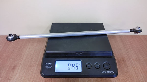
For the camber link, I simplified the design by using a tube with the ability to be threaded (instead of previously welded inserts). This will allow us to easily make lightweight aluminum backup components without having to weld and heat-treat the parts, leading to significant manufacturing time and cost reductions. This component weight reduced by 66% (0.37 lbm).
The only recorded failure during the competitions was during an exceed-design-load scenario of a sideways rollover at speed for the camber link. The H-frame never failed.

.jpg)
Left/Top: 17XT H-frame linkage design (4.6 lbm)
Right/Bottom: 18XT H-frame linkage design (3.3 lbm)
Note the reduction in number of tubes for manufacturing efficiency.


